A centrifugal pump develops bearing wear, but its maintenance dashboard continues reporting normal operation. The vibration sensor detects mechanical changes, yet the PLC exposes only a periodically updated RMS value. By the time the trend crosses the alarm threshold, the fault may already be advanced.
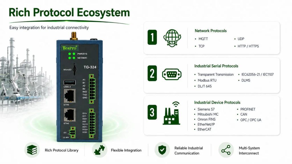
Installing an Industrial Gateway for Data Acquisition will not recover vibration details that were never measured. Its role is to transfer available condition data without introducing excessive delay, incorrect scaling, or missing records.
At Tespro, we consider three questions before recommending a gateway for predictive maintenance: what failure signatures must be captured, how frequently the source equipment updates them, and what information the monitoring platform needs to distinguish deterioration from normal load variation.
1. Which Equipment Signals Are Worth Collecting?
Predictive maintenance data requirements depend on the physical failure mechanism. A temperature trend may reveal lubrication problems in a gearbox, but it cannot reliably identify every early-stage bearing defect.
The acquisition architecture should match the diagnostic method.
| Equipment | Diagnostic signals | Acquisition limitation |
| Electric motors | Current, winding temperature, vibration | Current changes with mechanical load; temperature responds slowly |
| Centrifugal pumps | Flow, pressure, vibration, power | Process changes can resemble equipment degradation |
| Gearboxes | Vibration spectrum, temperature, shaft speed | Spectral interpretation depends on operating speed |
| Air compressors | Discharge temperature, pressure, current | Load/unload cycles distort simple trend thresholds |
Raw Waveforms vs Processed Condition Data
High-frequency vibration analysis normally requires dedicated acquisition hardware with appropriate sampling, filtering, and signal conditioning.
A gateway polling Modbus registers can retrieve vibration RMS, peak values, or calculated frequency features if the connected instrument exposes them. It cannot reconstruct the original acceleration waveform from an RMS register.
For practical applications, determine if your monitoring solution needs:
•Raw measurements: Continuous waveforms
•Calculated features: Post-processed data like RMS or spectral features
•Operating context: Equipment status and maintenance info to interpret/resolve alarm conditions
In a large-scale (distributed) system, you might be able to trade-off some flexibility for retrospective data analysis by having the gateway do less data post-processing and feature extraction.
2. How Fast Does the Gateway Need to Collect Data?
In most Modbus-based condition monitoring applications, it is not the gateway's data collection speed that will slow things down. It is more likely to be the field device polling cycle.
Modbus RTU acquisition time is determined by the serial baud rate, the length of the register count, the response length, device turnaround time, and communication errors.
A multi-device RS485 network can become unbalanced update cycle if one of the devices becomes unresponsive.
Estimate Complete Polling Cycle
Consider the following when selecting an industrial gateway:
•Source update interval: How often does the controller update the measured value?
•Bus occupancy: How many requests are needed to collect data from all connected devices?
•Timeout behavior: Will continuous errors from one instrument lead to a timeout for the remaining instruments?
•Acquisition priorities: Will the gateway support polling for condition tags for critical assets more frequently than the default for secondary operating parameters?
A good initial estimate is:
Total scan time = Transaction time + Turn around delay + Timeout/Retry overhead.
This estimate needs to be verified against the actual device population.
For Modbus TCP, Ethernet enables more flexible communication, but loading of the PLC and the number of concurrent request need to be assessed as well.
A one-second cloud reporting interval, for example, does not ensure one-second measurement freshness.
3. Prevent Data Conversion Errors from Becoming False Faults
Protocol conversion makes heterogeneous equipment accessible to a common monitoring platform. It also introduces opportunities for data corruption if register definitions are incomplete.
We consider here a 32-bit floating-point temperature stored across two Modbus registers. Incorrect word order can result in an invalid value even if communication was successful.
Scaling issues and register offsets can cause similar problems.
Data Quality Controls
•Register mapping: Verify functions codes, addresses, data types, and byte order against device documentation.
•Timestamp: Differentiate the time a measurement was made from the time it was transmitted to the gateway and the time it was transmitted to the cloud.
•Stale data: Set an invalid flag on data upon loss of a good acquisition; do not send outdated measurements.
•Equipment context: Assign a measurement to a piece of equipment, machine identity, location on equipment, and the equipment operating mode.
•Data continuity: Upon restoration of the network identify duplicates and data gaps.
Data quality controls are important even when using technologies such as OPC UA and MQTT.
In predictive maintenance, data quality controls, time stamps and data flags can be as important as actual sensor data.
4. Should Fault Detection Run at the Edge or in the Cloud?
It is advantageous to do local processing for equipment operating over a cellular network and/or if it's not practical to send every measurement to the cloud. For example, measurement filters and equipment-specific alarm thresholds can be done at the edge. The edge can also be used to determine abnormal events and/or trends.
Similar to motor current, evaluation of motor current should be done in the context of load rather than assessing faults in isolation.
What Happens When Connectivity Fails?
If the cellular connection is lost, continuous data delivery stops unless the architecture provides local storage.
MQTT QoS 2 supports exactly-once message delivery at the protocol level, but this does not guarantee exactly-once application processing or unlimited offline data retention. Buffering and recovery must be designed separately.
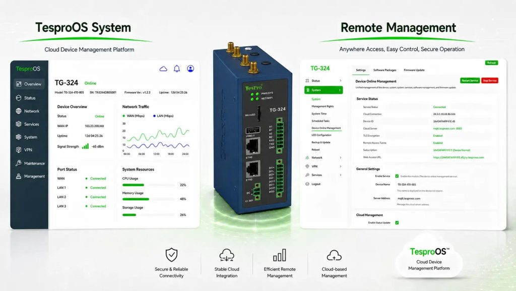
Tespro gateways are designed to integrate communications and industrial edge computing within an application. Local analytics, buffering, replay, and filtering should be assessed against the configuration and firmware of the gateways.
5. Selecting a Tespro Industrial Gateway for Data Acquisition
The TG-324 and TG-325 gateways offer industrial connectivity, Gigabit Ethernet and other protocols for machine condition monitoring.
Their published specifications include Modbus RTU/TCP, MQTT, OPC UA, and TesproOS-based management.
| Selection factor | TG-324 | TG-325 |
| Cellular connectivity | 2G/3G/4G | 2G/3G/4G/5G |
| Ethernet | Gigabit WAN + LAN | Gigabit WAN + LAN |
| Serial connectivity | 2 × RS485, 1 × RS232 | 2 × RS485, 1 × RS232 |
| Digital I/O | 4 configurable GPIO | 4 configurable GPIO |
| Industrial protocols | Modbus, MQTT, OPC UA | Modbus, MQTT, OPC UA |
| Main selection distinction | 4G-based remote installations | Sites requiring a compatible 5G uplink |
Both are candidates for consolidating data from compatible PLCs, sensors, and monitoring instruments.
The choice between 4G and 5G should depend on available carrier coverage, reporting traffic, uplink reliability, and deployment requirements—not an assumption that higher cellular bandwidth improves sensor accuracy.
For installations with multiple RS485 devices, protocol compatibility and aggregate polling performance may be more decisive.
6. What Should the Acceptance Test Demonstrate?
MQTT provides a way to test communication to the broker. However, it does not verify the quality of the information provided or its diagnostic value.
It is suggested that the entire acquisition path be exercised to cover operating conditions and failures.
•Measurement accuracy: Measurements should be compared to actual readings from the PLC (or other measuring devices) or check measurements throughout the operating range.
•Polling performance: The actual polling time for given device counts and register configurations should be measured.
•Communication failures: The behavior of the system should be observed during the loss of a field device, including the behavior of the system during retry events and the handling of stale data.
•Network recovery: The logged data should be reviewed to check if data is missing, duplicated, or out of order, and check the function of buffering is working as expected.
•Time consistency: Data is time synchronized across devices.
•Security and isolation: Access control and VPN, as well as other isolation mechanisms, should be checked.
Acceptance testing of data freshness, completeness, recovery, and loss should be defined prior to deployment. Predictive-model performance should be tested against a representative set of equipment condition data.
Tespro can assist with assessment of data connectivity for existing PLCs/instruments and remote condition monitoring. Please send your equipment count and register maps to our team.
Check out available configurations of Tespro Industrial Gateway Solutions.
FAQs
Q1. What is the role of a Tespro industrial gateway in predictive maintenance?
Tespro industrial gateways collect equipment data from compatible PLCs, sensors, and monitoring devices, then transmit it to edge or cloud-based maintenance platforms.
Q2. Which Tespro industrial gateways are suitable for predictive maintenance?
The TG-324 and TG-325 are candidates for industrial data acquisition. The TG-324 supports 4G connectivity, while the TG-325 adds 5G support.
Q3. Which industrial protocols do Tespro gateways support?
The TG-324 and TG-325 support Modbus RTU/TCP, MQTT, and OPC UA, enabling data exchange between industrial equipment and monitoring systems.
Q4. Can Tespro gateways collect data from existing PLCs?
Yes, when the PLC uses a supported communication protocol. Register mapping, data formats, polling intervals, and device compatibility must be verified before deployment.
Q5. Can Tespro gateways collect vibration and temperature data?
Yes, from compatible instruments that expose these measurements through supported interfaces. High-frequency vibration waveform capture may require dedicated acquisition hardware.